
Questions & Answers
Frequently asked questions
Getting started
How do I register my Polysun after the installation?
The registration of the program will require a license key and a valid internet connection. You will get your license key (EID) via e-mail after your (trial) order has been processed. You can enter the license key after starting Polysun.
Where can I see my license details after the installation?
Start Polysun and click on the «?» -> «Info» in the menu bar and then on the button «License». You will now be able to see your registration details (name and address), your user level (Standard, Designer or Premium) and your EID.
These license details aren’t visible to users using the server license. You can contact us anytime if you want to know more about your license.
I bought an upgrade, but do not see any difference in Polysun?
After buying an upgrade, it is important to refresh your license information to get access to the new features. To do so, please go to “Options” -> “add license”. You can use the same EID as before.
How do I create a support file?
The support file includes all important Polysun data needed to find and fix outstanding issues.
To create a Polysun support file, please click on «Support request» in the Polysun menu «?», then on «Create support file».
Alternatively, you can send us the data.log file, that you will find in the user data folder.
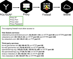
How do I allow connections if my company uses a firewall and/or proxy?
If your company uses a Firewall and/or Proxy, you must allow connections to www.velasolaris.com and secure.velasolaris.com (94.126.21.42) on Port 443 (HTTPS) and Port 80.
These settings can also be set inside the program via Settings-> Options -> Network
Report
How do I change the name in the report details?
In the PDF report, the user information is displayed in the title bar. This is composed of two entries:
- Name of the Polysun license owner. This information can be changed in the user.ini file. Open the “user.ini” file in the Polysun data directory. The data directory is located here by default:
- Windows: C:\Users\Public\Polysun
- MacOS: /Users/<username>/Library/Application Support/Polysun
- Linux: $HOME/.config/Polysun
Then find the lines with the entries “User.FirstName=” and “User.LastName=”. After the equal sign you can enter the desired name. If you leave it blank, nothing will be displayed. For example, if you enter User.FirstName=Max and User.LastName=Mustermann, then Max Mustermann will be displayed.
- Company name, phone number and e-mail: This information is entered in Polysun via “Options” -> “Settings” -> “Report”. There, you can also upload the company logo, which will then appear in the header of the report.
How do I upload my company logo?
The PDF report displays the user address in the header. To this section you can also upload your company logo.
- To upload your company logo in Polysun please go to «Options» -> «Settings» -> «Report»
- Please upload your company logo (jpg-format – optimal size: 150x90px). The logo will now be displayed in the header of the report.
Update
How and why should I update Polysun?
When Polysun is started, it checks whether a newer version is available. For Polysun to check whether an update is available, Polysun must have access to the Internet. If an update is available, a corresponding pop-up is displayed. If you do not want to perform the update, you can close the pop-up window. After that, Polysun will open normally.
To control the frequency of the automatic update search, you can click on “Options” and open “Settings”. The function is located under “Check for software updates”.
If needed, you can use the following steps to manually update Polysun to the latest version:
- With Polysun open, click on “Tools” in the main menu and click on “Check for software updates”.
- Or you can use the installation file on our homepage: https://www.velasolaris.com/downloads/.
In this way, you will benefit from new features, templates, catalog entries and bug fixes. In the release notes you can see the respective changes.
Components
How can I change component details in a variant, e.g. the tank volume?
A double-click on a symbol in the variant will open an info dialogue box that allows you to modify the features of the relevant components. Within this dialogue box the user will be able to modify all features for the use of such components (for example the orientation of collectors). Features directly relating to components (for example type of collector) may be defined over the catalogue. A double-click on the catalogue symbol will open a catalogue dialogue box that allows the user to change the relevant catalogue values. Starting from the Standard level version the software allows the user to create a new entry with the desired values.
What does auxiliary heating mean and how is it used?
In most cases solar systems are used as a back-up to conventional heating systems for water heating purposes. Whilst usually idle in the summertime auxiliary heating systems meet in the winter the larger share of the heating demand.
Auxiliary electric heaters are often times only used to reduce the use of boiler burners in the summertime. When a solar system is installed auxiliary electric heaters are usually dropped. In fact as electric power is expensive if compared to heating oil and gas users try at least to take advantage of more convenient off-peak electricity (this can be defined in the dialogue box). In Polysun auxiliary electric heating is implemented as an integral part of the tank whilst auxiliary heating with heating oil and gas appears as a separate component.
In Polysun operating hours and controllers may be defined just like in actual heating systems to the great possible extent. Controllers are used for this purpose (see below).
The amount of heated energy is defined as the «heated volume» times the difference between the temperature of hot and cold water (times the heating capacity of the fluid). The volume is defined by the overall content of the tank and the layer on which the electric heater is located.
Auxiliary heating may be controlled by means of two temperature sensors that may be placed freely over the electric heater. Cut-in and cut-off temperatures may be set separately (cut-in temperature should be, however, lower than the cut-off temperature). In the example the required hot water temperature is 50°C. Cut-off temperature should always be at least a few degrees higher than the former so that even after a few hours tank temperature will not drop too low. Finally electric heating will only come on when an outside temperature higher than 17°C is detected and, therefore, in the summertime.
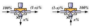
What’s the use of three-way valves?
Three-way valves play a crucial role when it comes to the analysis of fluid loops. Three-way valves share the inflowing fluid-flow in a fixed proportion. The position of the mixing valve is adjusted by the controller. Based on the situation in the schematic system diagram the three-way valve alternatively distributes inflowing fluid-flows or brings together two separate fluid flows. The adjusted output is marked with x. If the signal of the controller is logically one the x output will be completely open. Both situations are schematically outlined in the following graph:
What are fluids and how are they used in Polysun?
Polysun was designed so as to allow users to create the desired system layout by means of the available components. The first step of the simulation foresees hence a careful analysis of the system layout. The process includes in the sequence the identification of fluid domains and subsequently the identification of fluid loops.
Definition: The term Fluid refers to the fluid that circulates the different components and transports energy. As fluids often contain different substances Polysun includes a catalogue of main fluid components showing the pure substances (like, for example, water, ethylenglycol, propylenglycol) as well as a fluid mixture catalogue showing the fluids that are actually employed (like, for example, potable water, ethylene mixture, propylene mixture).
Definition: A fluid domain is a continuous hydraulic area permeated by a common fluid. A system typically consists of several different fluid domains. System components belonging to a defined fluid domain are circulated by the same fluid.
Definition: A fluid domain consists of one or more fluid loops. A fluid loop always includes a flow-rate producer. Results are given for fluid loops (not fluid domains).
The climatic characteristics of central Europe require solar systems to be able to withstand below freezing temperatures. This makes it impossible, for example, to produce the required amount of hot water directly in the collector. If pure tap water should freeze in the collector its expansion would destroy it. Normal tap water also shows a further disadvantage in that it may calcify the collector over the time.
For the heat transfer fluid to conform to the above-mentioned requirements the use of normal water mixed with a certain amount of glycol will be required. For this purpose in many cases ethylenglycol (for example Antifrogen L) or propylenglycol are employed as a frost protection agent. As the fluid circulates in a closed loop calcification problems are generally not an issue. As to the mixing ratio the following aspects will need to be considered:
- The heating capacity of the fluid decreases as glycol concentration grows
- Viscosity increases in case of higher glycol levels (pressure drop issue)
- The freezing point sinks as glycol concentrations grow
- The boiling point increases as glycol concentrations grow
- Possible chemical processes, especially in case of transition of different metals, should be carefully taken into account
- The fluid’s resistance to heat should be taken into account
Starting from a certain concentration freezing fluids no longer cause problems as they do not freeze into ice crystals but acquire instead a gelatinous-granular structure. An explosive effect may no longer intervene. The above effect may intervene starting from a volume proportion of 33 % (propylenglycol) or 38 % (ethylenglycol). Polysun allows the user to define glycol concentrations.
Simulation
What does «priority of control» mean?
Logic relation to other controls
In case multiple controllers access a common output (and only in this case) it will be necessary to define which is the logical link between the different signals. In this case in particular the identification of clear controller priorities will be crucial.
The list shown in the controller mask restores the priority of all controllers. The relevant controller will be identified as «this controller». Selecting a controller within the list the relevant controller will be listed directly ahead of the remaining controllers. Should two controllers be linked special care should be paid to ensure these appear consecutively in the list and that the link option is selected for the latter of the two. Options are as follows:
- And-Operation: if the current status is «on» and the relevant controller is likewise «on» the resulting status will be «on». When either status is «off» the output signal will be switched off.
- Or-Operation: if the current status is «on» or the relevant controller is likewise «on» the resulting status will be «on». If both statuses are «off» the output signal will remain «off».
- Exclusive-or-Operation: If the current status and the relevant controller are different the resulting status will be «on». If both statuses are alike the output signal will be switched off.
Priority of control
The list shown restores the priority of all controllers. The relevant controller will be identified as «this controller». Selecting a controller within the list the relevant controller will be listed directly ahead of the remaining controllers.
What does the message «No flow rate producer available» mean?
This error message can have various causes. There must be exactly 1 flow producer per fluid circuit. Series-connected pumps are not possible. If three-way valves are used at points where the flow direction is already defined, an overdefinition for the flow occurs.
Examples of different constellations that can lead to the problem:
– Two pumps in one fluid circuit
– Tap and pump in one fluid circuit
– Fluid circuit has no pump
– Component or pipe are not connected rum
– A circuit is divided with a T-piece, whereby it is not defined how the volume flow is divided. Replace T-piece with a mixing valve or 2 pumps on T-piece
– Stratifier lance not connected properly or fluid circuit of a stratified lance not closed
For visual examples see user manual, chapter 3.6.2.5.4.
Why does Polysun use a slightly too large value for the withdrawal volume?
It’s a matter of a deliberately allowed rounding error. The reference amount will be tapped with the design flow rate and a variable duration. For this purposes time units will be measure in seconds and always rounded up to whole seconds.
Why will an energy deficit result even in case of sufficient auxiliary heating?
When the hot water system is not running the water left in the pipes cools off. That’s why typically when first tapping water you will get a certain amount of too cold water. The resulting energy deficit will be added up and amounts as a rule to a monthly 2-5% of the energy demand.
What does the message «Energy demand not met» mean?
It may happen that the energy produced by the solar collectors and the auxiliary heating is insufficient to meet the energy demand of the planned system. In such cases, the temperatures of the domestic hot water and the building are different from the nominal values that were set in the project. Polysun marks these systems in the graphs and reports with the message «Energy demand not met».
To meet the demand, the energy consumer must be supplied with more solar thermal energy or auxiliary energy. In some cases, it is possible to obtain it by increasing the collector area or the power of non-solar auxiliary heating. However, the message «Energy demand not met» often means that the energy use is inefficient and the project must be revised.
How is the hot water withdrawal simulated?
The hot water withdrawal of a simulation will be defined through the following parameter:
- Nominal flow rate (for example 360 l/h)
- Daily profile (for example maximum daily peaks, that is for the 24 hours of the day in %: 0, 0, 0, 2.3, 2.3, 2.3, 2.3, 8, 8, 8, 2.3, 2.3, 8, 8, 8, 2.3, 2.3, 8, 8, 8, 2.4, 2.4, 2.4, 2.4)
- Daily hot water demand for single months (for example always 200 l/day from January to December)
In Polysun the amount of hot water that will be obtained during a given hour will always be determined at the beginning of such hour (for example 8% of the daily demand of 200 l, that is 16 litres, will be obtained in the morning between 8:00 and 9:00). In the Polysun simulation reference will always be made at the beginning of an hour to the total amount of hot water for such hour together with the nominal flow rate (in the above example 16 litres will be obtained with 360 litres/h that is water will be drawn for 2.66 minutes.
What are the definitions of the different solar fractions?
In the variant results display the user will be able to view the different solar fractions: Sfi (input-oriented), Sfn (net) and Sfg (gross). These refer to different limits of the system.
You can read more about the exact definitions in chapter 7.1.1 in our user manual, accessible via F1-key in the software.
Why isn’t the hot water energy demand constant in the component results?
Under energy demand the monthly energy demand will be listed in kWh. Since not all months have the same number of days monthly variations may be observed (for example February/March = 28/31).